PWM Mode
Overview
This mode is used to precisely generate PWM signal. PWM signal is the endless chain of identical rectangular pulses. In other words, PWM signal is periodical signal, each cycle is a rectangular pulse. PWM signal is composed of low-level signal and high-level signal.
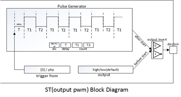
A block diagram of ST in pwm mode is as follows:
Available Commands
| Command | Sub Command | Description | |||
|---|---|---|---|---|---|
| set | mode | output | pwm | set mode: PWM | |
| div | sec | set unit: second | |||
| ms | set unit: millisecond | ||||
| us | set unit: microsecond | ||||
| output | od | open-drain | |||
| pp | push-pull | ||||
| low | output LOW | ||||
| high | output HIGH | ||||
| dev | uio0 | #pin | set output device and pin | ||
| invert | 0 | not invert output | |||
| 1 | invert output | ||||
| count | [T1] [T2] | set output timing parameters | |||
| delay | [D] | set delay | |||
| trigger | from | st# | set trigger target: st0 ~ st7 | ||
| php | set trigger target: none | ||||
| reset | - | reset | |||
| get | state | get current state | |||
| start | - | start | |||
| stop | - | stop | |||
Set Count Values
In output PWM mode, this command is used to specify the low-level duration and high-level duration. The unit of time is specified in "set div" command.
| Command | Syntax |
|---|---|
| set count | pid_ioctl($pid, "set count T1 T2"); |
Available count values in pwm mode are as follows:
| Unit | Available Count Values (0 ~ half an hour) |
|---|---|
| microsecond | 0, 10 ~ 1,800,000,000 |
| millisecond | 0 ~ 1,800,000 |
| second | 0 ~ 1,800 |
This command must be used before timer starts. If not, an error is generated.
The figure below shows waveform of PWM signal
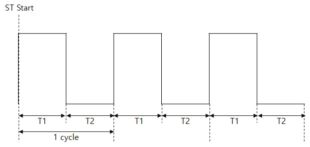
※ Duty cycle = T1 / (T1 + T2)
※ Frequency = 1 / (T1 + T2)
Set Output [dev D N]
| Command | Syntax |
|---|---|
| set output dev D N | pid_ioctl($pid, "set output dev uio0 0"); |
Before using output mode of ST, you must use this command to specify the output pin. Set a device name (e.g. uio0) and a pin number to D and N.
Set Output [low/high]
This command immediately forces ST pin to LOW or HIGH.
| Command | Syntax | Description |
|---|---|---|
| set output low | pid_ioctl($pid, "set output low"); | Set ST pin to LOW |
| set output high | pid_ioctl($pid, "set output high"); | Set ST pin to HIGH |
Note that if invert mode is enabled, this command will force ST pin to the state that is invert of normal operation.
Set Output [od/pp]
This command set output type of ST pin
| Command | Syntax | Description |
|---|---|---|
| set output pp | pid_ioctl($pid, "set output pp"); | Set output type to push-pull |
| set output od | pid_ioctl($pid, "set output od"); | Set output type to open-drain |
If the command is not used, the output type of ST pin is push-pull by default.
Set Output Invert [0/1]
This command is used to enable/disable invert mode.
| Command | Syntax | Description |
|---|---|---|
| set output invert 0 | pid_ioctl($pid, "set output invert 0"); | disbale invert mode |
| set output invert 1 | pid_ioctl($pid, "set output invert 1"); | enable invert mode |
When invert mode is enabled:
- output signal in ST pin will be inverted in compassion with the normal operation.
- "set output high" and "set output low" are also inverted.
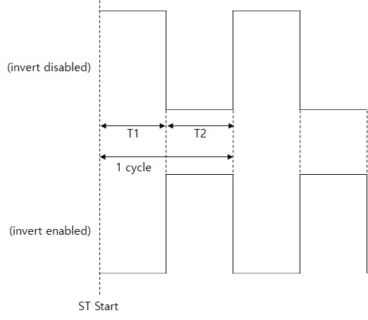
Invert mode is disabled by default.
Set Trigger
This command is used when you want to synchronize an ST start time with another ST. Target of trigger should be one of ST devices.
| Target | Syntax |
|---|---|
| ST(st0/1…) | pid_ioctl($pid, "set trigger from st0"); |
| php | pid_ioctl($pid, "set trigger from php"); |
Default value of trigger target is "php"(no target).
Example of PWM Mode
example of PWM mode
<?php
$pid = pid_open("/mmap/st0"); // open ST 0
pid_ioctl($pid, "set div sec"); // set unit: second
pid_ioctl($pid, "set mode output pwm"); // set mode: PWM
pid_ioctl($pid, "set output dev uio0 0"); // set output dev / pin: uio0 / 0
pid_ioctl($pid, "set count 1 1"); // set count values: 1 and 1
pid_ioctl($pid, "start"); // start ST
sleep(10);
pid_ioctl($pid, "stop"); // stop ST
pid_close($pid);
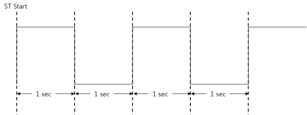
?>The figure below shows waveform of the example above.