Layout
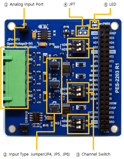
1. Analog Input Port
The analog input port is a port for inputting analog signals. The input signal can be selected as voltage or current depending on whether the input type jumper is connected or not.
| Type | Range(Unit) |
|---|---|
| Voltage (DC) | 0 ~ 5(V) |
| Current | 0 ~ 20(mA) |
This port is 1-by-6 terminal block with 5mm pitch.
| lable | port number | input type jumber |
|---|---|---|
| IN0+, IN0- | Input Port #0 | JP4 |
| IN1+, IN1- | Input Port #1 | JP5 |
| IN2+, IN2- | Input Port #2 | JP6 |
2. Input Type Jumper(JP4, JP5, JP6)
You can use these jumpers to select the type of input signal for each port.
| jumper connection | description |
|---|---|
| connected | current input |
| disconnected | voltage input |
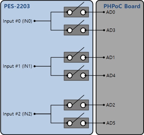
3. Channel Switch
The channel switch connects the analog signals from the PES-2203 to the PHPoC board.
Each input port can be connected with one or two ADC channels.
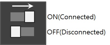
When the switch is positioned in the direction of the arrow, it is ON and when it is positioned in the opposite direction of the arrow, it is OFF.
4. JP7
The PHPoC board is factory-shipped with an VDDA-AREF jumper, which basically inputs DC 3.3V into the analog input reference. If you do not have an VDDA-AREF jumper, you can use the 3.3V voltage as the analog input reference voltage via the PES-2203 by connecting JP7 of the PES-2203.
※ Caution: If the VDDA-AREF jumper on the PHPoC board and this jumper are connected at the same time, it may cause the product to malfunction. Therefore, before connecting JP7, make sure that the VDDA-AREF jumper on the PHPoC board is NOT connected.
5. LED
The PWR LED is on the PES-2203 board. This LED is always on when power is supplied to the board.