Layout
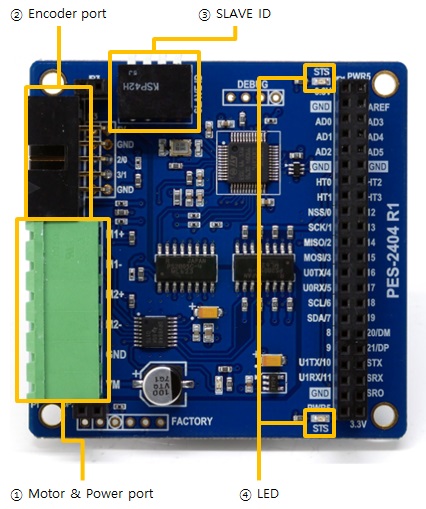
1. Motor & Power port
This port is for connecting PES-2404 to motor and the motor's power supply. It has six terminals and a 5mm pitch.
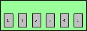
| Number | Name | I/O | Description |
|---|---|---|---|
| 0 | M1+ | Out | Motor port 1, positive(+) |
| 1 | M1- | Out | Motor port 1, negative(-) |
| 2 | M2+ | Out | Motor port 2, positive(+) |
| 3 | M2- | Out | Motor port 2, negative(-) |
| 4 | GND | - | Power supply for motors (Ground) |
| 5 | VM | In | Power supply for motors (DC 4 ~ 18V) |
2. Encoder port
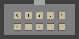
This port is for connecting encoders.
| Number | Name | I/O | Description |
|---|---|---|---|
| 0 | 5V | Out | Power supply for encoders (DC 5V) |
| 1 | GND | - | Power supply for encoders (Ground) |
| 2 | 1A | In | Encoder A phase for motor port 1 |
| 3 | 1B | In | Encoder B phase for motor port 1 |
| 4 | GND | - | Power supply for encoders (Ground) |
| 5 | 5V | Out | Power supply for encoders (DC 5V) |
| 6 | GND | - | Power supply for encoders (Ground) |
| 7 | 2A | In | Encoder A phase for motor port 2 |
| 8 | 2B | In | Encoder A phase for motor port 2 |
| 9 | GND | - | Power supply for encoders (Ground) |
※ 1A, 1B, 2A and 2B are internally pulled up.
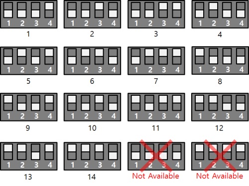
3. SLAVE ID Switch
A slave ID is used when PHPoC board identifies each smart expansion board. So, each smart expansion board, which is connected to a PHPoC board, should have a unique slave ID. The slave ID can be set one of the numbers from 1 to 14 by 4 DIP switches as follows:
4. LED
The PES-2404 board has two STS LEDs. The one, on the top of the board, is connected to 3.3V and the other one, on the bottom of the board is connected to 5V. The operations of both LEDs are the same and they are as follows:
| State | Operation |
|---|---|
| Normal | Repeat On/Off in every second |
| Invalid slave ID | Blinks very quickly |
| Fail to communicate with PHPoC | Off |