Layout
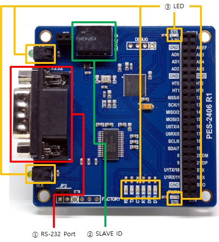
1. RS-232 Port
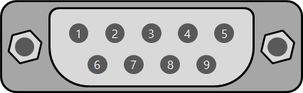
The RS-232 port of the PES-2406 is a D-SUB 9-pin male connector. The pin map is as follows.
| Number | Name | Description | Level | I/O | Wiring |
|---|---|---|---|---|---|
| 1 | DCD | Data Carrier Detect | RS-232 | In | Optional |
| 2 | RXD | Receive Data | RS-232 | In | Required |
| 3 | TXD | Transmit Data | RS-232 | Out | Required |
| 4 | DTR | Data Terminal Ready | RS-232 | Out | Optional |
| 5 | GND | Ground | Ground | - | Required |
| 6 | DSR | Data Set Ready | RS-232 | In | Optional |
| 7 | RTS | Request To Send | RS-232 | Out | Optional |
| 8 | CTS | Clear To Send | RS-232 | In | Optional |
| 9 | RI | Ring Indicator | RS-232 | In | Optional |
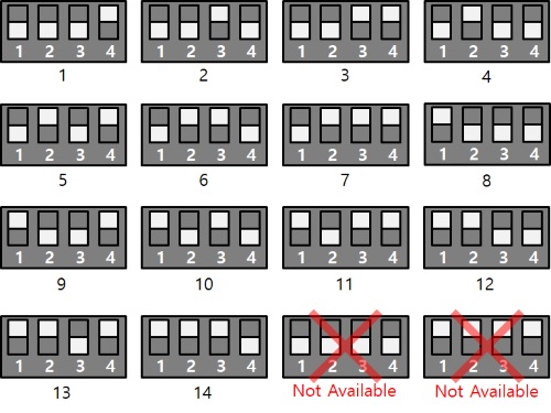
2. SLAVE ID Switch
A slave ID is used when PHPoC board identifies each smart expansion board. So, each smart expansion board, which is connected to a PHPoC board, should have a unique slave ID. The slave ID can be set one of the numbers from 1 to 14 by 4 DIP switches as follows:
3. LED
PES-2406 has 10 LEDs. Two of these are STS LEDs that indicate the status of the board. The one, on the top of the board, is connected to 3.3V and the other one, on the bottom of the board is connected to 5V. The rest eight of them are LEDs indicating various states of serial communication. The operation and meanings of each LED are as follows:
| Name | Quantity | Type | Color | Operation |
|---|---|---|---|---|
| STS | 2 | SMD | Red | ID setting is normal > Repeated on / off every 1 second ID setting is incorrect > Fast flashing |
| TX | 2 | DIP, SMD | Green | Blinks when sending data to the serial port |
| RX | 2 | DIP, SMD | Yellow | Blinks when receiving data to the serial port |
| CTS | 1 | SMD | Yellow | On when CTS signal is ON |
| RTS | 1 | SMD | Green | On when RTS signal is ON |
| DSR | 1 | SMD | Yellow | On when DSR signal is ON |
| DTR | 1 | SMD | Green | On when DTR signal is ON |