Layout
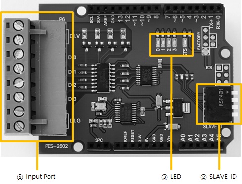
1. Input Ports
Input ports are interfaced with a 5mm spaced terminal block which has 8 terminals. Every output port is isolated by photocoupler and supports wet contact, dry contact, NPN transistor and PNP transistor input.
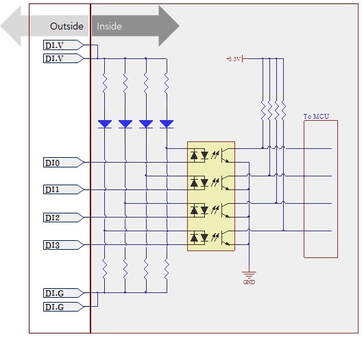
Circuit Diagram of Input Port
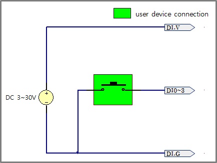
WET contact
Voltage conditions in wet contact is as follows:
| division | condition |
|---|---|
| maximum DC input | DC 30V |
| ON | more than DC 3V |
| OFF | less than DC 1.5V |
Refer to the following figure for connection with your device.
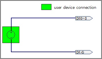
Dry contact
An input port is ON under being short circuit between the port and DI.G port in this type. It means additional power should be supplied between DI.V and DI.G. Refer to the following figure for connection with your device.
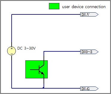
NPN Transistor Connection
Refer to the following figure for connection with an NPN transistor.
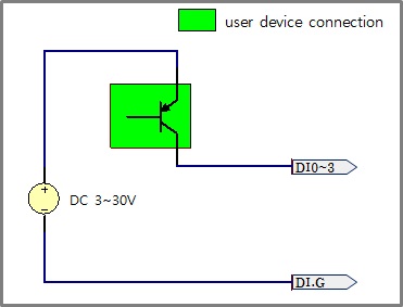
PNP Transistor Connection
Refer to the following figure for connection with a PNP transistor.
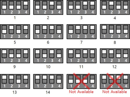
2. SLAVE ID Switch
A slave ID is used when PHPoC shield identifies each smart expansion board. So, each smart expansion board, which is connected to a PHPoC shield, should have a unique slave ID. The slave ID can be set one of the numbers from 1 to 14 by 4 DIP switches as follows:
3. LED
This board has five LEDs.
| LED | Description |
|---|---|
| STS | when slave id is valid > repeat on and off every second when slave id is invalid > blinks very quickly when it failed to communicate with a PHPoC shield > off |
| 0 | turned ON with input 0 is ON |
| 1 | turned ON with input 1 is ON |
| 2 | turned ON with input 2 is ON |
| 3 | turned ON with input 3 is ON |