Layout
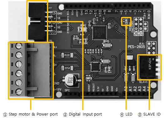
1. Stepper motor & Power port
Stepper motor & Power port is a terminal block. It has six terminals and a 5mm pitch.
| label | description |
|---|---|
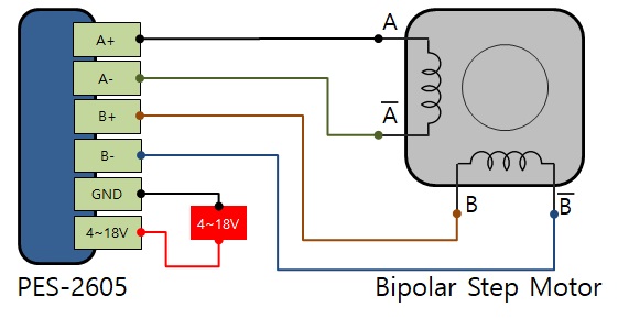
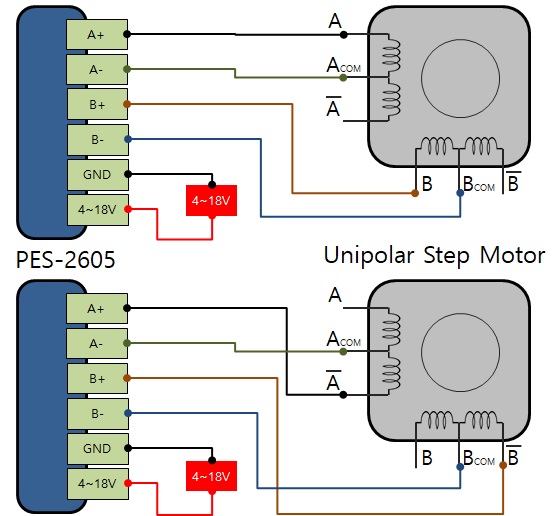
| A+, A-, B+, B- | connect to stepper motor |
| 4~18V, GND | connect to power |
Connecting to a bipolar stepper motor
This board is a bipolar stepper motor controller. An example of connection with a bipolar stepper motor is as follows:
Connecting to a unipolar stepper motor
If you want to connect a unipolar stepper motor to this board refer to two examples below.
Supplying power
The GND pin and the 4~18V pin are input port of supplying power(DC 4 ~ 18V) to run motors. Supplying power through this port is positively necessary. Check the DC polarity when you input the power.
2. Digital input port
This port is used to connect limit switches and cannot be used for other purposes.
An example of connection with limit switches is as follows:
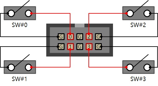
- G means ground and all ground pins are connected each other
- 0, 1, 2 and 3 are the index number of input ports and all of them are pulled up
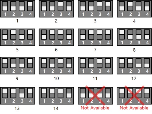
3. SLAVE ID Switch
A slave ID is used when PHPoC shield identifies each smart expansion board. So, each smart expansion board, which is connected to a PHPoC shield, should have a unique slave ID. The slave ID can be set one of the numbers from 1 to 14 by 4 DIP switches as follows:
4. LED
This board has STS LED which indicates the board's status.
| State | Operation |
|---|---|
| ready | Repeat On/Off in every second |
| running | shortly blink 4 times every second under OFF state |
| locked | shortly blink every second under ON state |
| Fail to communicate with PHPoC shield | Off |