Layout
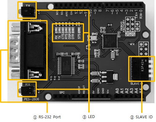
1. RS-232 Port
The RS-232 port of this board is a D-SUB 9-pin male connector. The pin map is as follows.
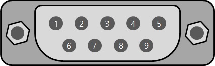
| Number | Name | Description | Level | I/O | Wiring |
|---|---|---|---|---|---|
| 1 | DCD | Data Carrier Detect | RS-232 | In | Optional |
| 2 | RXD | Receive Data | RS-232 | In | Required |
| 3 | TXD | Transmit Data | RS-232 | Out | Required |
| 4 | DTR | Data Terminal Ready | RS-232 | Out | Optional |
| 5 | GND | Ground | Ground | - | Required |
| 6 | DSR | Data Set Ready | RS-232 | In | Optional |
| 7 | RTS | Request To Send | RS-232 | Out | Optional |
| 8 | CTS | Clear To Send | RS-232 | In | Optional |
| 9 | RI | Ring Indicator | RS-232 | In | Optional |
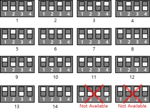
2. SLAVE ID Switch
A slave ID is used when PHPoC shield identifies each smart expansion board. So, each smart expansion board, which is connected to a PHPoC shield, should have a unique slave ID. The slave ID can be set one of the numbers from 1 to 14 by 4 DIP switches as follows:
3. LED
This board has 9 LEDs.
| Name | Quantity | Type | Color | Operation |
|---|---|---|---|---|
| STS | 1 | SMD | red | ID setting is normal > repeats on / off every 1 second ID setting is incorrect > blinks fast |
| TX | 2 | DIP, SMD | green | blinks when sending data to the serial port |
| RX | 2 | DIP, SMD | yellow | blinks when receiving data to the serial port |
| CTS | 1 | SMD | yellow | ON when CTS signal is ON |
| RTS | 1 | SMD | green | ON when RTS signal is ON |
| DSR | 1 | SMD | yellow | ON when DSR signal is ON |
| DTR | 1 | SMD | green | ON when DTR signal is ON |