Layout
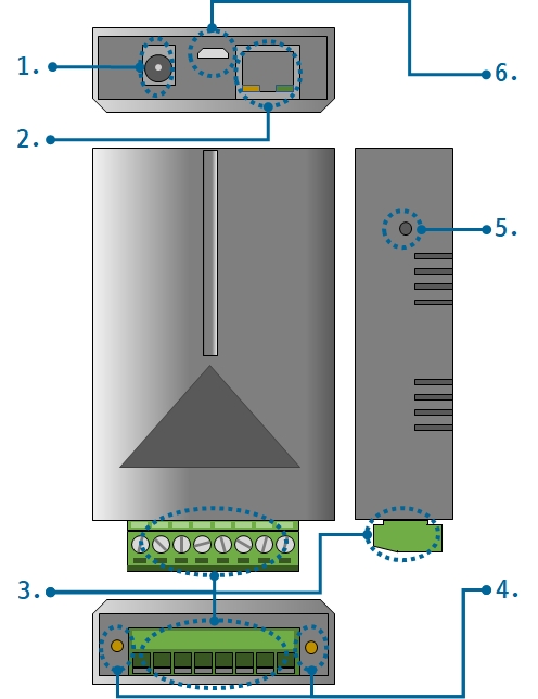
1. Supplying Power
-
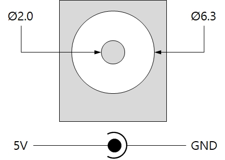
DC 5V Input
This port is the input port for supplying power. The input voltage is DC 5V(±0.2V) and the specification is as follows:
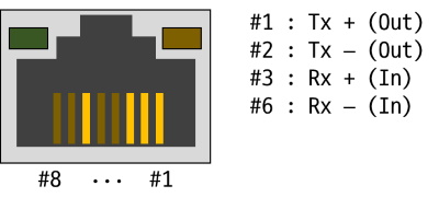
2. Ethernet
Ethernet port supports 10/100Mbps Ethernet. This port is an RJ45 connector and it is mapped to NET0 for programming.
3. Analog Input
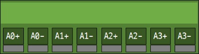
4 analog input ports are an 8-pole (3.5mm pitch) terminal block. Each port is mapped 0 to 3 channel of ADC device(ADC0/1/2) for programming. You must the input type of the each port. The input type will be voltage(DC 0 ~ 5V) when you output LOW to each input type select pin. On the other hand, the input type will be currentcurrent (0 ~ 20mA) when you output HIGH to the pin.
| Port | Lable | Port assignment | Type select pin |
|---|---|---|---|
| Input 0 | A0+, A0- | ADC0/1/2 ch.#0 | UIO0.16 |
| Input 1 | A1+, A1- | ADC0/1/2 ch.#1 | UIO0.17 |
| Input 2 | A2+, A2- | ADC0/1/2 ch.#2 | UIO0.18 |
| Input 3 | A3+, A3- | ADC0/1/2 ch.#3 | UIO0.19 |
4. LED
This product has 4 LEDs. The user-defined LEDs are turned on when you output LOW to the UIO pin connected.
| Lable | Color | Description | UIO pin |
|---|---|---|---|
| A | Green | User-defined LED | UIO0.30 |
| B | Green | User-defined LED | UIO0.31 |
| RJ45_G | Green | System LED - system status | N/A |
| RJ45_Y | Yellow | System LED - network link status | N/A |
5. Function Button
The function button, which is inside the hole of the side panel, is used to operate this product as a button setup mode.
6. USB Device Port for connection with PC
The USB device port is to connect with PC. You can access to P5H-153 via development tool by connecting USB cable to this port.