Layout
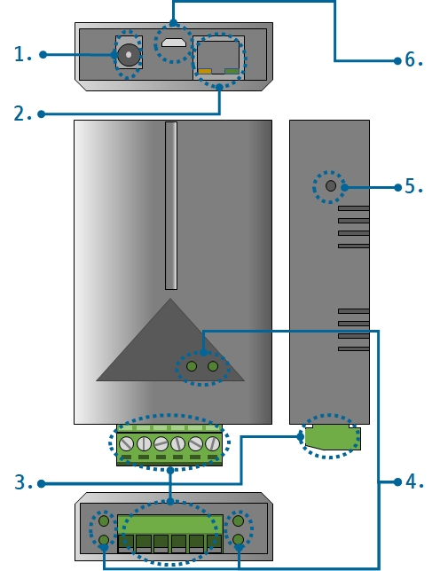
1. Supplying Power
-
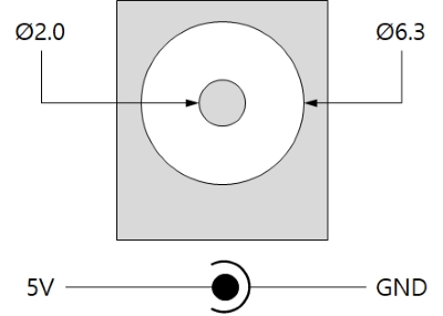
DC 5V Input
This port is the input port for supplying power. The input voltage is DC 5V(±0.5V) and the specification is as follows:
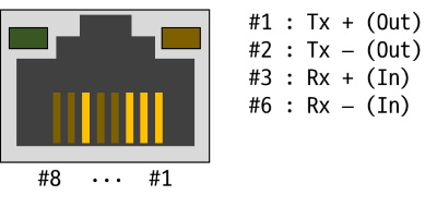
2. Ethernet
Ethernet port supports 10/100Mbps Ethernet. This port is an RJ45 connector and it is mapped to NET0 for programming.
3. Digital Input
4 digital input ports are an 6-pole (3.5mm pitch) terminal block. Each port is mapped a specific pin of UIO0 for programming.
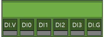
| Lable | Description | UIO pin |
|---|---|---|
| DI.V | common voltage input, DC 4.5V ~ 25V | - |
| DI0 | digital input #0 | UIO0.22 |
| DI1 | digital input #1 | UIO0.23 |
| DI2 | digital input #2 | UIO0.24 |
| DI3 | digital input #3 | UIO0.25 |
| DI.G | common ground | - |
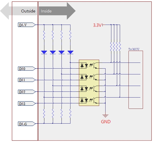
Circuit Diagram of the Digital Input Port
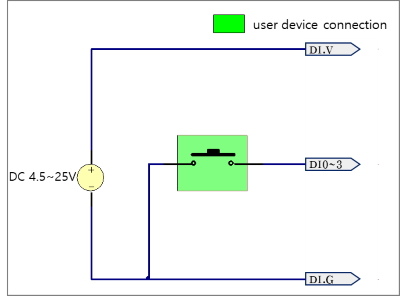
WET contact
The condition of input voltage is as follows:
| division | voltage |
|---|---|
| maximum input voltage | DC 25V |
| minimum input voltage for ON state | DC 4.5V or higher |
| maximum input voltage for OFF state | DC 1V or lower |
Refer to the following figure for connection with your device.
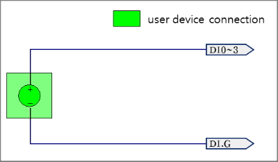
Dry contact
An input port is ON under being short circuit between the port and DI.G port in this type. It means additional power should be supplied between DI.V and DI.G. Refer to the following figure for connection with your device.
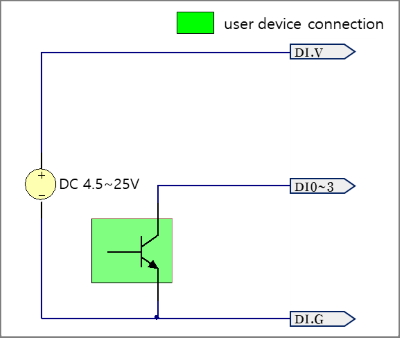
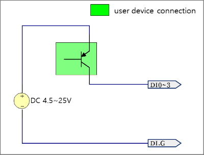
NPN Transistor Connection
Refer to the following figure for connection with an NPN transistor.
PNP Transistor Connection
Refer to the following figure for connection with a PNP transistor.
4. LED
This product has 8 LEDs. The user-defined LEDs are turned on when you output LOW to the UIO pin connected.
| Lable | Color | Description | UIO pin |
|---|---|---|---|
| L0 | Green | User-defined LED | UIO0.30 |
| L1 | Green | User-defined LED | UIO0.31 |
| Di0 | Green | System LED - status of input port #0 | UIO0.22 |
| Di1 | Green | System LED - status of input port #1 | UIO0.23 |
| Di2 | Green | System LED - status of input port #2 | UIO0.24 |
| Di3 | Green | System LED - status of input port #3 | UIO0.25 |
| RJ45_G | Green | System LED - system status | N/A |
| RJ45_Y | Yellow | System LED - network link status | N/A |
5. Function Button
The function button, which is inside the hole of the side panel, is used to operate this product as a button setup mode.
6. USB Device Port for connection with PC
The USB device port is to connect with PC. You can access to P5H-154 via development tool by connecting USB cable to this port.