Layout
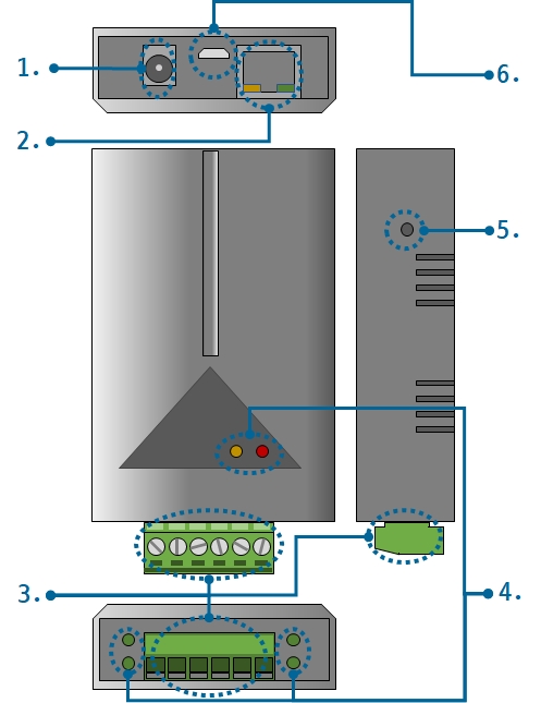
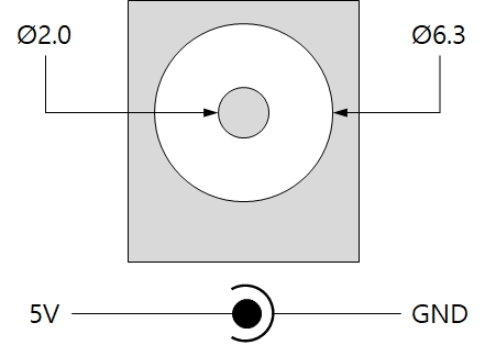
1. Supplying Power
-
DC 5V Input
This port is the input port for supplying power. Specification is as follows:
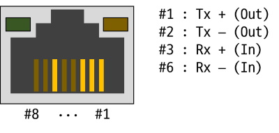
2. Ethernet
Ethernet port supports 10/100Mbps Ethernet. This port is an RJ45 connector and it is mapped to NET0 for programming.
3. Digital Output
2 digital output ports are an 6-pole(5mm pitch) terminal block. Each port is mapped a specific pin of UIO0 for programming.
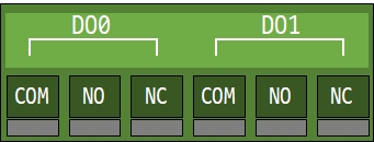
| Port | Description | Terminals | UIO pin |
|---|---|---|---|
| DO0 | digital output port #0 | COM, NO, NC | UIO0.0 |
| DO1 | digital output port #1 | COM, NO, NC | UIO0.1 |
Normal Open
It means that the output port default is OFF. This method can be used by connecting user equipment to COM terminal and NO terminal of each output port. The maximum allowable current is 5A at DC 30V.
Normal Close
It means that the output port default status is ON. This method can be used by connecting user equipment to COM terminal and NC terminal of each output port. The maximum allowable current is 1A at DC 30V.
4. LED
This product has 8 LEDs. The user-defined LEDs are turned on when you output LOW to the UIO pin connected.
| Lable | Color | Description | UIO pin |
|---|---|---|---|
| PWR | Red | System LED - power supplying status | - |
| STS | Yellow | System LED - system status | - |
| A | Green | User-defined LED | UIO0.30 |
| B | Green | User-defined LED | UIO0.31 |
| Do0 | Green | System LED - status of input port #0 | UIO0.0 |
| Do1 | Green | System LED - status of input port #1 | UIO0.1 |
| RJ45_G | Green | System LED - network link status | - |
| RJ45_Y | Yellow | System LED - system status | - |
5. Function Button
The function button, which is inside the hole of the side panel, is used to operate this product as a button setup mode.
6. USB Device Port for connection with PC
The USB device port is to connect with PC. You can access to P5H-155 via development tool by connecting USB cable to this port.