Evaluation Board
This evaluation board is only can be used with P4M-400.
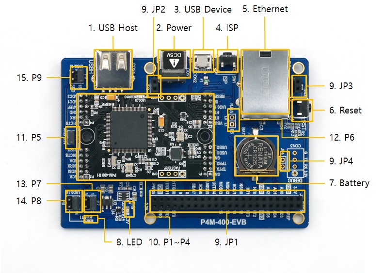
1. USB Host Port for Connection with WLAN adapter
This board provides a USB host port for an USB WLAN adapter. You can connect P4M-400 to 802.11b/g wireless LAN by connecting a wireless LAN adapter to this port.
※ Caution: Only adapters using Ralink RT3070/5370 chipsets are available.
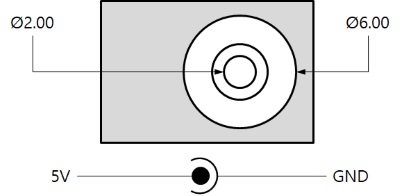
2. Power
-
DC 5V Input
This port is the main input port for supplying power(DC 5V). Specification is as follows:
-
USB Device port (Micro USB)
This port can be a sub input port for supplying power. P4M-400 may not work properly in case of supplying power via this port only due to insufficient current.
3. USB Device Port for connection with PC
The USB device port is to connect with PC. You can access to P4M-400 via the development tool(PHPoC Debugger) by connecting USB cable to this port. You can supply DC 5V power through this port.
4. ISP Button
If this button is pressed, LOW signal is connected to the ISP# pin.
5. Ethernet
This port provides 10/100Base-TX Ethernet interface of P4M-400. Internal LEDs (L0 and L1) can be operated by connecting jumper on P6. The LEDs are LOW active.
6. Reset Button
If this button is pressed, LOW signal is connected to the RESET# pin.
7. Battery
The CR1225 of RENATA is embedded as battery for RTC. The battery socket is also compatible with CR1220.
※ Refer to the datasheet for more information about the battery
8. LED
There are two LEDs on this board.
| LED | Color | Description |
|---|---|---|
| 3.3V | red | supplying power > ON |
| P8 connected LED | green | user-defined LED |
9. JP1 / JP2 / JP3 / JP4
| Name | Description |
|---|---|
| JP1 | PHPoC board-compatible interface socket |
| JP2 | PHPoC board-compatible socket |
| JP3 | PHPoC board-compatible socket |
| JP4 | reserved |
The pin numbers of JP1 are as follows:
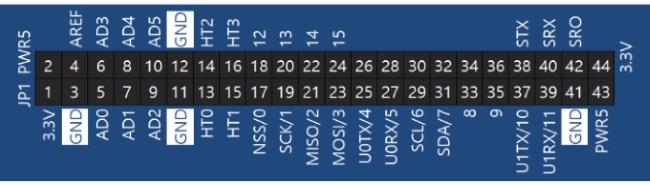
※ JP1, JP2 and JP3 are designed to connect expansion boards for PHPoC boards.
10. P1 / P2 / P3 / P4
P1, P2, P3 and P4 are ports to connect P4M-400.
※ Note : The positions of the P1 to P4 connectors are designed asymmetrically to prevent miss insertion and reverse insertion of the module.
11. P5
If the jumper on this port is connected, 3.3V is supplied as a reference voltage pin (AREF) for ADC.
12. P6
It is a connector for signal input to LED on RJ45. Pins are connected to the L0 and L1 pins of the RJ45. The LEDs are LOW active.
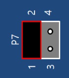
13. P7
This port is reserved for the future use. Keep the jumper position on 1 and 2.
14. P8
This port is for selecting usage of UIO0.14 of P4M-400. The UIO0.14 can be connected to the 22th pin(14) of JP1 or the user-defined LED.
| Jumper position | Description |
|---|---|
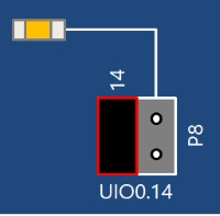 |
connect UIO0.14 to the 22th pin of JP1(14) |
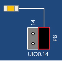 |
connect UIO0.14 to the user-defined LED |
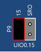
15. P9
The UIO0.15 is connected to the 24th pin of JP1(15). Be sure to connect jumpers as shown in the following figure.