Layout
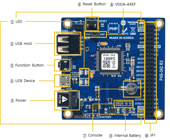
1. LED
There are six LEDs on the P4S-342 board.
| LED | Action |
|---|---|
| PWR / 3.3V / PWR5 | supplying power > ON |
| STS | running PHP > repeat On and Off in every second not running PHP > briefly blinks 1 time at a time |
| UIO30 | on board LED: connected with 30th pin of UIO0 |
| UIO31 | on board LED: connected with 31th pin of UIO0 |
※ PWR, STS, UIO30 and UIO31 are also located on the opposite side.
2. USB Host Port for Connection with WLAN adapter
P4S-342 provides a USB host port for an USB WLAN adapter. You can connect P4S-342 to Wireless LAN by connecting an WLAN adapter to this port.
※ Caution: Only adapters using Ralink RT3070/5370 chipsets are available.
3. Function Button (Func)
The function button is used for changing mode to the Button setup mode.
4. USB Device Port for connection with PC
The USB device port is to connect with PC. You can access to P4S-342 via development tool by connecting USB cable to this port. You can supply DC 5V power through this port. However, P4S-342 may not work properly in case of supplying power via this port only due to insufficient current.
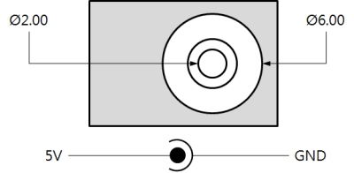
5. Supplying Power
-
DC 5V Input
This port is the main input port for supplying power. Specification is as follows:
-
USB Device port (Micro USB)
This port can be a sub input port for supplying power.
6. Reset Button (RESET)
This button is used for hardware reset.
7. Console Port
This port is console port for management.
| Division | Value |
|---|---|
| Signal Level | 3.3V |
| Configuration | 115,200bps / 8 Data bit / 1 Stop bit / No parity |
| Pin Assignment | #1 - 3.3V, #2 - RX, #3 - TX, #4 - GND |
8. JP1
| Label | Description | Label | Description |
|---|---|---|---|
| 3.3V | 3.3V Output | PWR5 | Output Supplied Power (5V±0.5V) |
| GND | Ground | AREF | ADC reference input port |
| AD0 | ADC channel 0 | AD3 | ADC channel 3 |
| AD1 | ADC channel 1 | AD4 | ADC channel 4 |
| AD2 | ADC channel 2 | AD5 | ADC channel 5 |
| GND | Ground | GND | Ground |
| HT0 | Hardware Timer 0 | HT2 | Hardware Timer 2 |
| HT1 | Hardware Timer 1 | HT3 | Hardware Timer 3 |
| NSS/0 | SPI - NSS / UIO0 #0 | 12 | UART #1 RTS / UART #1 TxDE / UIO0 #12 |
| SCK/1 | SPI - SCK / UIO0 #1 | 13 | UART #1 CTS / UIO0 #13 |
| MISO/2 | SPI - MISO / UIO0 #2 | 14 | UIO0 #14 |
| MOSI/3 | SPI - MOSI / UIO0 #3 | 15 | UIO0 #15 |
| U0TX/4 | UART #0 TX / UIO0 #4 | 16 | UIO0 #16 |
| U0RX/5 | UART #0 RX / UIO0 #5 | 17 | UIO0 #17 |
| SCL/6 | I2C - SCL / UIO0 #6 | 18 | UIO0 #18 |
| SDA/7 | I2C - SDA / UIO0 #7 | 19 | UIO0 #19 |
| 8 | UART #0 RTS / UART #0 TxDE / UIO0 #8 | 20/DM | UIO0 #20 |
| 9 | UART #0 CTS / UIO0 #9 | 21 | UIO0 #21 |
| U1TX/10 | UART #1 TX/ UIO0 #10 | STX | SPC TX |
| U1RX/11 | UART #1 RX/ UIO0 #11 | SRX | SPC RX |
| GND | Ground | SRO | SPC Reset |
| PWR5 | Output Supplied Power (5V±0.5V) |
3.3V | 3.3V Output |
9. VDDA-AREF
If you connect this port, 3.3V is supplied to the analog input reference port (AREF).
10. Internal Battery
Internal battery is for saving log messages and operating RTC. Specification of this battery is as follows:
| Parameter | Value |
|---|---|
| Capacity | 5.8mAh |
| Nominal Voltage | DC 3V |
| Charge Voltage | DC 2.8V ~ 3.1V |
※ Refer to the datasheet for more information about the battery