Layout
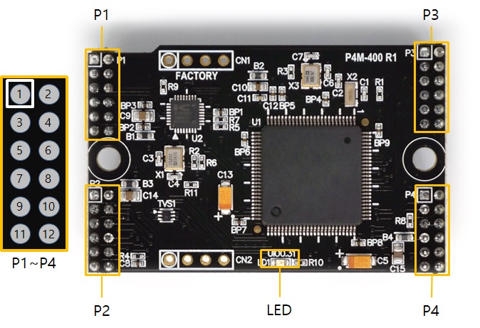
The P4M-400 interfaces with four 6 x 2-pin headers (P1 to P4). Space of each pin is 2 mm.
P1
| Pin# | Name | I/O | Description |
|---|---|---|---|
| P1.1 | GND | - | Ground |
| P1.2 | GND | - | Ground |
| P1.3 | TPTX+ | In/Out | Ethernet Transmit + |
| P1.4 | TPTX- | In/Out | Ethernet Transmit - |
| P1.5 | TPRX+ | In/Out | Ethernet Receive + |
| P1.6 | TPRX- | In/Out | Ethernet Receive - |
| P1.7 | GND | - | Ground |
| P1.8 | GND | - | Ground |
| P1.9 | USB_H_D+ | In/Out | USB Host Data + |
| P1.10 | USB_H_D- | In/Out | USB Host Data - |
| P1.11 | USB_D_D+ | In/Out | USB Device Data + |
| P1.12 | USB_D_D- | In/Out | USB Device Data - |
P2
| Pin# | Name | I/O | Description |
|---|---|---|---|
| P2.1 | VBUS | In | USB Device VBUS |
| P2.2 | +3.3V | - | +3.3V Power Input |
| P2.3 | HT0(1.6) | In/Out | UIO 1.6 / Hardware Timer/Counter 0 |
| P2.4 | HT1(1.7) | In/Out | UIO 1.7 / Hardware Timer/Counter 1 |
| P2.5 | HT2(1.8) | In/Out | UIO 1.8 / Hardware Timer/Counter 2 |
| P2.6 | HT3(1.9) | In/Out | UIO 1.9 / Hardware Timer/Counter 3 |
| P2.7 | UIO(0.14) | In/Out | UIO 0.14 |
| P2.8 | SRO(0.15) | In/Out | UIO 0.15 / Slave Reset Out |
| P2.9 | ISP# | In | ISP Input (Active LOW) |
| P2.10 | DTX | Out | Debug Out (UART) |
| P2.11 | RESET# | In | Reset Input (Active LOW) |
| P2.12 | VBAT | In | Battery Input |
P3
| Pin# | Name | I/O | Description |
|---|---|---|---|
| P3.1 | NSS(0.0) | In/Out | UIO 0.0 / SPI NSS |
| P3.2 | SCK(0.1) | In/Out | UIO 0.1 / SPI SCK |
| P3.3 | MISO(0.2) | In/Out | UIO 0.2 / SPI MISO |
| P3.4 | MOSI(0.3) | In/Out | UIO 0.3 / SPI MOSI |
| P3.5 | U0TX(0.4) | In/Out | UIO 0.4 / UART0 TX |
| P3.6 | U0RX(0.5) | In/Out | UIO 0.5 / UART0 RX |
| P3.7 | SCL(0.6) | In/Out | UIO 0.6 / I2C SCL |
| P3.8 | SDA(0.7) | In/Out | UIO 0.7 / I2C SDA |
| P3.9 | U0RTS(0.8) | In/Out | UIO 0.8 / UART0 RTS / UART0 TxDE |
| P3.10 | U0CTS(0.9) | In/Out | UIO 0.9 / UART0 CTS |
| P3.11 | U1TX(0.10) | In/Out | UIO 0.10 / UART1 TX |
| P3.12 | U1RX(0.11) | In/Out | UIO 0.11 / UART1 RX |
P4
| Pin# | Name | I/O | Description |
|---|---|---|---|
| P4.1 | U1RTS(0.12) | In/Out | UIO 0.12 / UART1 RTS / UART1 TxDE |
| P4.2 | U1CTS(0.13) | In/Out | UIO 0.13 / UART1 CTS |
| P4.3 | STX(1.10) | In/Out | UIO 1.10 / Slave TX |
| P4.4 | SRX(1.11) | In/Out | UIO 1.11 / Slave RX |
| P4.5 | GND | - | Ground |
| P4.6 | GND | - | Ground |
| P4.7 | +3.3V | - | +3.3V Power Input |
| P4.8 | AREF | In | ADC Reference Input |
| P4.9 | ADC0(1.0) | In/Out | UIO 1.0 / ADC0 |
| P4.10 | ADC1(1.1) | In/Out | UIO 1.1 / ADC1 |
| P4.11 | ADC2(1.2) | In/Out | UIO 1.2 / ADC2 |
| P4.12 | ADC3(1.3) | In/Out | UIO 1.3 / ADC3 |
LED
At the bottom center of the module is the user-defined LED. This LED is connected to UIO 0.31 and is set to LED for status display at the factory. It can be set to the user output port if necessary, and when the LOW is output, the LED is turned on.